Home | LTE in General | Fractional Frequency Reuse | Integrated Femto & Macrocell Environments | Forward Error Correction | MBSFN | Our Team | Downloads
Long Term Evolution (LTE) telecommunication system constitutes the next step beyond third generation mobile networks and a step behind the fourth generation mobile standard. LTE supports scalable carrier bandwidths, from 20 MHz down to 1.4 MHz and provides downlink peak rates of at least 100 Mbps and round-trip times less than 10 ms. LTE introduces several techniques in order to achieve increased performance.
LTE networks offer high capacity and are specified and designed to accommodate small, high performance, power-efficient end-user devices. The investigation of inter-channel interference mitigation techniques has become a key focus area in achieving dense spectrum reuse in next generation cellular systems. Fractional Frequency Reuse (FFR) has been proposed as a technique to overcome this problem, since it can efficiently utilize the available frequency spectrum.
LTE standard achieves considerable advancements in system capacity and throughput, but the deployment of macro cells results in high operational and capital expenditures. A way to increase cost-capacity of the networks is to deploy a large number of smaller and cheaper cells, i.e. femtocells which improve coverage in indoors, contributing to offload the macro network, yet very important considering that a large amount of wireless traffic is originated in indoors.
Furthermore, the evolved Multimedia Broadcast and Multicast Services (e-MBMS) feature constitutes the evolutionary successor of MBMS for LTE systems. The key motivation for integrating multicast and broadcast extensions into mobile communication systems is to enable efficient group related data distribution services, especially on the radio interface.
Finally, to meet the error free transmission requirement of demanding multicast applications, 3GPP recommends the use of the systematic, fountain Raptor code as an Application Layer FEC (AL-FEC) protection mechanism exclusively for MBMS, In order to meet the error free transmission requirement of demanding applications, 3GPP recommends the use of the systematic, fountain Raptor code as an Application Layer FEC (AL-FEC) protection mechanism exclusively for MBMS providing enhanced reliability control over LTE multicast services.
The result of the LTE standardization by 3GPP is the evolved packet system (EPS) that consists of the core network (CN), named evolved packet core (EPC), and the radio access network (RAN), named evolved universal terrestrial radio access network (eUTRAN). EPC can also be connected to other 3GPP or non-3GPP radio access networks.
The EPC consists of three nodes, one control-plane node, named mobility management entity (MME), and two user-plane nodes, named serving gateway (S-GW) and packet data network gateway (P-GW). The eUTRAN consists of the base stations, called evolved NodeB (eNB), that are connected to each other through the X2 interface and to the EPC through the S1 interface. Finally, the mobile terminals are denoted as user equipment (UE).
The architecture of EPC, with only two user-plane nodes, is simpler than the predecessor UMTS architecture consisting by four user-plane nodes. Subsequently, some of the UTRAN radio network controller (RNC) functionalities, such as ciphering and header compression, are performed by the eNB in LTE. Furthermore, handovers between eNBs are now performed through packet forwarding over the X2 interface.

Fractional Frequency Reuse (FFR) in LTE Networks
Long Term Evolution (LTE) networks offer high capacity and are specified and designed to accommodate small, high performance, power-efficient end-user devices. The investigation of inter-channel interference mitigation techniques has become a key focus area in achieving dense spectrum reuse in next generation cellular systems. Fractional Frequency Reuse (FFR) has been proposed as a technique to overcome this problem, since it can efficiently utilize the available frequency spectrum.
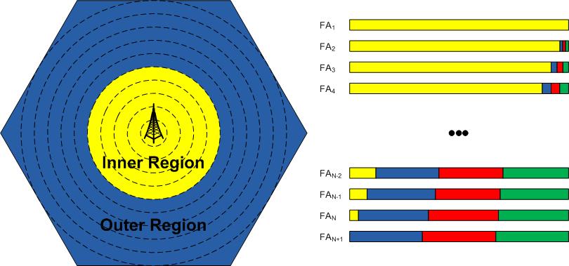
In FFR the cell space is divided into two regions: inner, which is close to the Base Station (BS) and outer, which is situated to the borders of the cell.
The whole frequency band is divided into several sub-bands, and each one is differently assigned to inner and outer region of the cell respectively. As a result of FFR, intra-cell interference is eliminated, and inter-cell interference is substantially reduced. At the same time the system throughput is enhanced. Various reuse factors and interference mitigation levels can be achieved by adjusting either the bandwidth proportion assigned to each region or the transmission power of each band.
In FFR, in order to ensure that the mutual interference between users and BSs remains below a harmful level, adjacent cells use different frequencies. In fact, a set of different frequencies are used for each cluster of adjacent cells. Cluster patterns and the corresponding frequencies are reused in a regular pattern over the entire service area. The closest distance between the centers of two cells using the same frequency (in different clusters) is determined by the choice of the cluster size and the layout of the cell cluster. This distance is called the frequency reuse distance.
One of the main objectives of LTE is to achieve high spectral efficiency, meaning the use of the whole of the system’s bandwidth in all cells. This approach is called Frequency Reuse 1 and is considered as the simplest scheme: all sub-bands of the available bandwidth are allocated to each cell. In Frequency Reuse 3, the system bandwidth is divided into 3 equal sub-bands; each one of these is allocated to cells in a manner that no other surrounding cell is using the same sub-band. Full frequency reuse in each cell can exempt the necessity of advance frequency planning among different cells, and the frequency reuse patterns can be dynamically adapted on a frame-by-frame basis in each cell.
Integrated Femto & Macrocell Environments
New wireless standards such as 3GPP’s High Speed Packet Access (HSPA) and Long Term Evolution (LTE) achieve considerable advancements in system capacity and throughput, but the deployment of macro cells results in high operational and capital expenditures. A way to increase cost-capacity of the networks is to deploy a large number of smaller and cheaper cells, i.e. femtocells.
Femtocells will improve coverage in indoors, contributing to offload the macro network, yet very important considering that a large amount of wireless traffic is originated in indoors. In addition, femtocells will use a cheaper backhaul connection: internet.
Not surprisingly, the case of femtocells has gained enormous support from the industry since it can represent a more cost-effective solution for wireless network operators than traditional deployments.
Deployment of femtocells represents a promising solution to increase cost-capacity benefits for network operators and provide higher data rates to end-users. Femtocells are conceived to provide indoor wireless access to a cellular network through a Home Base Station, which is connected via internet to the operator’s core network, helping to improve coverage in indoors, offload the macrocell and reduce costs for operators.
However, large scale deployment of femtocells can severely interfere with the existing macrocell within which they are deployed, particularly when operating in co-channel or in immediate adjacent channels with respect to the macrocell and when using a closed access policy. For instance, macrocell coverage holes in the downlink will appear, i.e. zones in the vicinity of a home base station where interference from home base station signals will prevent macrocell users to receive the desired service from the macrocell network.

Forward Error Correction on 3GPP MBMS
A crucial point on the provision of reliability over mobile multicast delivery is the use of a Forward Error Correction (FEC) scheme on the application layer. FEC, unlike the common methods for error control is not based on lost or corrupted packets retransmission, since the error correction is "forward" in the sense that redundant data are transmitted in advance with the source information, in order to obtain the receivers the ability to overcome packet losses. The application of FEC on ptm reliability protocols provides particular advantages. The most important property of FEC codes is the ability to use the same FEC packets to repair simultaneously different independent packet losses at multiple receivers, without the need of the costly or impossible procedure of packets retransmission. In order to meet the error free transmission requirement of demanding applications, 3GPP recommends the use of the systematic, fountain Raptor code as an Application Layer FEC (AL-FEC) protection mechanism exclusively for MBMS.
The 3GPP multicast services standard, named MBMS, is a unidirectional ptm service in which data are transmitted from a single source to a group of multiple mobile endpoints in a specific service area. 3GPP defines two delivery methods namely, download and streaming.
Download uses the FLUTE protocol which is carried over UDP/IP and is independent of the IP version and the underlying link layers used. In order to apply AL-FEC protection on the MBMS download delivery, the transmitted file is partitioned in one or several source blocks each consisting of k source symbols. For each source block, redundant repair symbols are generated through FEC encoding with a unique ID assigned on each resulting encoding symbol. Subsequently, one or more encoding symbols are placed in each FLUTE packet payload with the resulting packets encapsulated in UDP and distributed over the IP multicast flow.
On streaming delivery, RTP is the application layer protocol which provides means for sending real-time or streaming data over UDP transport layer. The MBMS AL-FEC streaming framework operates on RTP/UDP flows. A copy of the source packets is forwarded to the Raptor encoder and arranged in a source block with each packet occupying a new row of T bytes. The source block is filled up to k rows, where the value of k can be different for each source block. After forming a FEC source block from the packets to be protected together, the Raptor encoder generates the desired repair symbols which are then sent using the FEC repair packet format.

Multicast/Broadcast Single Frequency Network (MBSFN)
The evolved Multimedia Broadcast and Multicast Services (e-MBMS) feature constitutes the evolutionary successor of MBMS for Long Term Evolution (LTE) systems. The key motivation for integrating multicast and broadcast extensions into mobile communication systems is to enable efficient group related data distribution services, especially on the radio interface.
To improve the multimedia data delivery, LTE has exploited the Orthogonal Frequency-Division Multiplexing (OFDM) radio interface to transmit MBMS data as a multicell transmission over a synchronized Single Frequency Network (MBSFN).
A key new feature of LTE is the possibility to exploit the OFDM radio interface to transmit multicast or broadcast data as a multicell transmission over a synchronized Single Frequency Network: this is known as Multimedia Broadcast Single Frequency Network (MBSFN) operation.
MBSFN transmission enables a more efficient operation of the MBMS service, allowing over-the-air combining of multi-cell transmissions towards the User Equipment (UEs).
In MBSFN operation, MBMS data is transmitted simultaneously over the air from multiple tightly time-synchronized cells. A UE receiver will therefore observe multiple versions of the signal with different delays due to the multicell transmission. Provided that the transmissions from the multiple cells are sufficiently tightly synchronized for each to arrive at the UE within the cyclic prefix at the start of the symbol, there will be no Inter Symbol Interference (ISI). In effect, this makes the MBSFN transmission appear to a UE as a transmission from a single large cell, and the UE receiver may treat the multicell transmissions in the same way as multipath components of a single-cell transmission without incurring any additional complexity. The UE does not even need to know how many cells are transmitting the signal.
This Single Frequency Network reception leads to significant improvements in spectral efficiency compared to UMTS Release 6 MBMS, as the MBSFN transmission greatly enhances the SINR. This is especially true at the cell edge, where transmissions which would otherwise have constituted inter-cell interference are translated into useful signal energy - hence the received signal power is increased at the same time as the interference power being largely removed.

- Christos Bouras (Professor) [home page]
- Vasileios Kokkinos (Computer and Informatics Engineer, PhD)
Old Members:
- Andreas Papazois (PhD, Computer & Informatics Engineer)
- Nikos Kanakis (MSc, PhD candidate, Computer & Informatics Engineer)
- Georgia Tseliou (Undergraduate Student)
- Dimitrios Bilios (Undergraduate Student)
- Anastasios Bikos (Undergraduate Student)
- Konstantinos Asimakis (Undergraduate Student)
- Konstantinos Kontodimas (Undergraduate Student)
- George Tsichritzis (MSc, Computer & Informatics Engineer)
Additional information about the members of our team are available in the People area of the website, where full CVs as well as the publications and the projects that they participate is available.
AL-FEC integration on ns-3
In order to simulate the application of an AL-FEC protection scheme over 3GPP MBMS environments, we utilize the ns-3 network simulator.
The AL-FEC protection (based on Raptor codes) is modeled on the application source before the transmitted data being forwarded to the core network. More precisely, according to the specified Source Block Length of the FEC block the transmitted packets are organized in AL-FEC source blocks and thereafter the redundant AL-FEC symbols are produced for each source block. The number of the generated additional AL-FEC symbols is determined by the transmission overhead a multicast sender introduces to the transmission. Thereafter, the generated source and repair symbols are transmitted through an IP multicast flow to multiple recipients.
You can download the source code of ns-3 including the AL-FEC integration from here.
Tool for MBSFN area optimization based on spectral efficiency and cost
We have developed a tool (in Lua programming language) which optimizes the MBSFN area configuration based on one of the following two parameters: spectral efficiency and total telecommunication cost.
In the first case the tool estimates the spectral efficiency (SE) of each cell, the resource efficiency (RE) of the network and gradually formulates the optimal network deployment that maximizes the network’ s RE. The algorithm starts with an arbitrary distribution of MBSFN cells (for a given interested UE drop area) and then makes random changes to it. For every change it calculates the RE of the system, if it has decreased, it rolls back to the best-known configuration. In many cases though, the changes happen to be beneficial for the RE and thus they are accepted. Gradually, this procedure leads to better configurations. In the case of optimizing the MBSFN area configuration based on the total telecommunication cost, the main idea is to sequentially compare the intermediate calculated costs until we find the minimum total one.
The tool implementing this procedure is available here.
Implementation in Matlab for FFR optimization in OFDMA networks
Our team has developed a Matlab simulation for OFDMA networks. We propose a dynamic FFR mechanism that selects the optimal frequency allocation and inner cell radius based on the cell total throughput and a custom metric which is called user satisfaction (US). In detail, the mechanism divides the cell into two regions (inner and outer). For each potential frequency allocation (FA), the mechanism calculates the per-user throughput, the cell total throughput and US. This procedure is repeated for successive inner cell radius. Afterwards, the mechanism selects the optimal FFR scheme that maximizes the cell total throughput and US.
The source code for the implementation of the above procedure is available here.
A throughput simulation framework for LTE-A systems
One of out latest projects is a MATLAB simulation framework for throughput calculation in every possible point within a LTE Advanced macrocell range. The framework allows user to add buildings in the topology and deploy femto base stations (BSs) in custom spots. Buildings' walls are taken into account for the path loss estimation, derived in case they interfere between the BS and the user equipment (UE), while the rest of BSs cause interference. The user may be attached to the macro or a femto BS. Simulation calculates throughput and other userful information like the SINR and the path loss, for every possible user location.
You can download source code from here.
An admission control simulation framework for LTE-A OFDMA Small Cell networks
Our research team has developed a Matlab simulation environment for OFDMA small cell networks. Firstly, we propose a novel power control mechanism that performs power selection and adaptation among the most efficient power algorithms in LTE-A small cells. The latter results in the most efficient and beneficial usage of energy radio resources. Secondly, with the possibility to co-function together with a Quality-of-Service (QoS) traffic provisioning algorithm, besides power control, real-time multimedia traffic, for instance High-Definition, becomes optimally differentiated. Plotting results show that total throughput capacity is augmented, and delay is minimized.
You can download source code from here.
If you need any help please contact the project team.